Combustion chamber
Moderator: Mike Everman
Re: Combustion chamber
Propane injectors is just 7 ~0.7mm holes in O shape 5mm tubing. Holes looks toward to combustion chamber front, you can see that in first sketch. I market them with 2 lines at top and bottom
-
Johansson
- Posts: 1161
- Joined: Sun Nov 21, 2004 9:42 pm
- Antipspambot question: 0
- Location: Northern Sweden
Re: Combustion chamber
So the injector ring is inside the combustor can where the flame zone is? It is bedtime here in Sweden so I might be a bit slow, but I am not really able to picture how it looks like.
Re: Combustion chamber
Yes, injetor ring is inside the combustion chamber. The problem is that flame out is not in all turbine output, but about 45degrees of it.
-
Johansson
- Posts: 1161
- Joined: Sun Nov 21, 2004 9:42 pm
- Antipspambot question: 0
- Location: Northern Sweden
Re: Combustion chamber
Aha, the general use of the word flame out is when the flame blows out completely.
To me it looks like you have too much hole area at the front of the combustor so the air blows directly at the propane injector, for all I´ve learned from reading around (I have not built a micro turbine myself) there should be a "calm" spot right behind the combustor front plate where the flame zone can settle without being blown out by the incoming air.
How are you testing the combustor? Any pics of the arrangement?
Re: Combustion chamber
Thanks, Johansson. I tested not a seperate CC, but all engine. I think, i will try to make new CC.
-
Johansson
- Posts: 1161
- Joined: Sun Nov 21, 2004 9:42 pm
- Antipspambot question: 0
- Location: Northern Sweden
Re: Combustion chamber
Ok, so you had the engine assembled when you ran it? How could you see the flame in the CC then?Ainis wrote:Thanks, Johansson. I tested not a seperate CC, but all engine. I think, i will try to make new CC.
I will check my computer for some useful info regarding micro turbine combustor designing and send a PM to you!
Re: Combustion chamber
I saw flame not in the combustor output, but in engine output. I think the problem is that fuel ring holes are too small, that makes gas speed higher than burning speed and that makes that the gas can't ignite at a combustor begining. I'll try to makes holes biger, and drill more of them.
-
Johansson
- Posts: 1161
- Joined: Sun Nov 21, 2004 9:42 pm
- Antipspambot question: 0
- Location: Northern Sweden
Re: Combustion chamber
quote="Ainis"]I saw flame not in the combustor output, but in engine output. I think the problem is that fuel ring holes are too small, that makes gas speed higher than burning speed and that makes that the gas can't ignite at a combustor begining. I'll try to makes holes biger, and drill more of them.[/quote]
How is your total hole area compared to the compressor inlet area? You should keep the hole area about the same as the inlet area, if the hole area is much larger you will have combustion problems since the ability to guide the incoming air by the hole pattern is lost. Then the air will just go the easiest route and parts of the combustor won´t get any air flow at all.
What is your e-mail adress?
Re: Combustion chamber
No, i talked not about combustor holes, but about gas delivery ring. Mine e-mai is AinisStel@gmail.com or skype BLITZ-as
Thanks.
Thanks.
-
Johansson
- Posts: 1161
- Joined: Sun Nov 21, 2004 9:42 pm
- Antipspambot question: 0
- Location: Northern Sweden
Re: Combustion chamber
Ah, my mistake. 
You´ve got mail!
You´ve got mail!
Re: Combustion chamber
Thanks Johansson for mail.
I drilled about 14holes in size of 1.5mm in fuel ring, And it looks that now it works better, but not good enough. I think tomorow i will try to drill more holes
I drilled about 14holes in size of 1.5mm in fuel ring, And it looks that now it works better, but not good enough. I think tomorow i will try to drill more holes
-
Johansson
- Posts: 1161
- Joined: Sun Nov 21, 2004 9:42 pm
- Antipspambot question: 0
- Location: Northern Sweden
Re: Combustion chamber
How are you spooling up the turbine while testing? Shop air, leaf blower?
Does it start picking up speed when you turn up the propane flow or does it just throw flames through the turbine?
Does it start picking up speed when you turn up the propane flow or does it just throw flames through the turbine?
Re: Combustion chamber
Iam spooling it with shop air. No, now it dont speed up, It just throw flame through the turbine, but i think more holes in fuel ring maybe will make better job.
check the mail, i wrote my story
check the mail, i wrote my story
Re: Combustion chamber
Now fuel ring has ~30holes 2.5mm diameter. Today I starded the engine. It seems that engine can sustain its speed, but NGV and turbine wheel starts to glow red. EGT is over 800C. If I help engine to acelerate with shop air, glowing disapiers but only until engine is rotating at higher speed from its rotor inertia. When I disassembled the engine, I can see that primary combustion zone didn't saw a lot of heat:
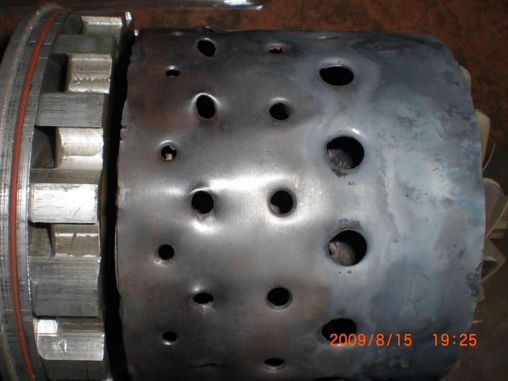
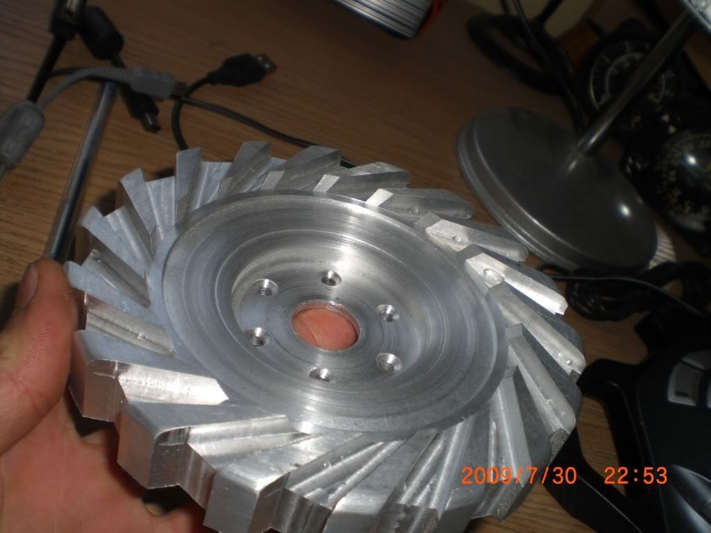
Is it could be a diffuser problem, or its combustor problem? Difusser was machined from solid, and it has pretty wide wanes:
Ainis.
Is it could be a diffuser problem, or its combustor problem? Difusser was machined from solid, and it has pretty wide wanes:
Ainis.
-
racketmotorman
- Posts: 503
- Joined: Sat Jul 23, 2005 11:11 pm
- Antipspambot question: 0
- Location: Australia
Re: Combustion chamber
Hi Anis
The engine won't work with that diffuser, the "blunt" tips will cause all sorts of problems , they need to be triangular and come to a point at the inlet end , and they must be at the correct angle relative to the airflow .
Also I think I saw somewhere in your Thread that you used a 25 degree NGV angle ,this could be too great an angle for the components being used resulting in a high flow from the comp but at reduced efficiency , the reduced efficiency requiring more power from the turbine wheel and generally higher temperatures .
Fix your diffuser first , then go back to your original fuel ring with the small holes facing the front wall of the FT which must have the correct sizing and distribution of holes to match your comps flow (inducer area) .
Cheers
John