Been a while - new project, T04 Gas Turbine.
Moderator: Mike Everman
-
Fricke
- Posts: 325
- Joined: Tue Mar 01, 2005 8:17 pm
- Antipspambot question: 125
- Location: Southern Sweden
- Contact:
Wow!
That´s a really beautiful piece of engine you have made!
"woot"
A shrill, obnoxious noise/word used by immature people to express happiness or excitement.
Supposedly started in the gamer community, but is now used by any slack-jawed moron to express delight.
A shrill, obnoxious noise/word used by immature people to express happiness or excitement.
Supposedly started in the gamer community, but is now used by any slack-jawed moron to express delight.
-
Ash Powers
- Posts: 176
- Joined: Sat Sep 04, 2004 7:17 am
- Antipspambot question: 0
- Location: Edgewater, FL
- Contact:
Re: nice job
Definately - I've had the furnace and sand molding equipment for a little over a year now and it has been great being able to produce the parts you've seen some samples of, but it wasn't until I bought my Grizzly Lathe/Mill machine that all of it has really taken off. Being able to cast your components and then precision machine the castings to desired shape has opened up many new possibilities in a cost-effective manner. Before I had the mill/lathe, I was paying out the whazoo to have the local CNC shop machine my castings and other parts. About 50% of the components in this current GT I'm building came from castings and all of the machining has been done in my garage here on the mill/lathe. My total investment in parts for the engine itself have mostly been in the price of the compressor wheel and turbine/shaft. In raw materials, I've probably only got $100 in it, tops. I've managed to melt all of the alumiunum for the castings on one tank of propane and still have about 1/4" tank left of the LPG. If I had purchased billet aluminum to machine these parts from, I would have at least doubled the materials cost figure. I have a 54-gallon drum full of aluminum railing scraps, which are all clean metal too - got that barrel of scraps from my welding shop for free too! :) I've used about half of it already so somewhere around 100lbs of aluminum have been melted down in that little furnace.skyfrog wrote:Gee, that's really fun with a furnace and sand moulding equipment in house !
Building the furnace/cart and obtaining the other casting equipment (petrobond molding sand, parting dust, clay-graphite crucible), as well as building the molding flasks and tongs to hold the crucicble wasn't terribly expensive - I think there is about a total of $250 in the whole setup - the 100lb bag of petrobond being the single most expensive component (~$150). It is small and compact and the sandbox only takes up a little room in the garage - for any home-builder/fabricator, having a furnace and sand casting equipment combined with a lathe/mill will gear you for building just about anything. :) Good times!
-
Mike Everman
- Posts: 5007
- Joined: Fri Oct 31, 2003 7:25 am
- Antipspambot question: 0
- Location: santa barbara, CA
- Contact:
-
Ash Powers
- Posts: 176
- Joined: Sat Sep 04, 2004 7:17 am
- Antipspambot question: 0
- Location: Edgewater, FL
- Contact:
Mike,
There is a TON of information on the web about how to build your own furnace. I can't recall where I found it exactly, but there is a page on what exact mixture you need to produce the refractory liner. I know it is a mix of fire clay, portland cement, pearlite, and silica sand, in specific proportions. It is mixed up much like concrete, although a good bit thicker in consistency. You literally have to "ram" it into your furnace casing and give it a few days to cure. As I'm sure you can tell, I made the furnace casing from an old propane tank. The tank was completely empty of propane gas and I drilled a small hole in the top of it and filled it with water to evacuate any lingering propane gases and then proceeded to cut the top off with a jigsaw and metal cutting blade. After the refractory liner set and cured after a few days, it was fired up and run at low gasflow to "bake" the liner to cook off all of the remaining water still in it.
Amazingly enough, even after melting down a full 6lbs of aluminum (which only takes about 10 minutes), the outer casing is just barely warm. :)
There is also a ton of information out there on constructing the burner tube (it is just simple pipe and two pipe adapters with a propane feed tube with a single hole drilled as a nozzle for the LPG to inject into the tube, of which the parts are available at any hardware store.
I've been happy with the Grizzly unit - it is quite well constructed even given that it was made in China for Grizzly. One of the best investments I made last year. :)
-
Zippiot
- Posts: 1190
- Joined: Tue Nov 15, 2005 7:55 pm
- Antipspambot question: 0
- Location: california
- Contact:
heck the forum on this site for much other help
http://backyardmetalcasting.com/
I made a dolomite refractory that could be used to melt steels, if I could ever get the heat that high...
Well an easy dolomite refractory (has to be fired to hold its shape well) is just a 50/50 mix of sand and dolomite. You can use silica sand if you want a 3k F+ temp refract but you will never go that high!
Otherwise you can find a standard fireclay refract on the site.
Sailing Student- How do I know if my life jacket is tight enough?
Me- Can you breathe?
Sailing Student- Yes
Me- Then its too loose!
Me- Can you breathe?
Sailing Student- Yes
Me- Then its too loose!
-
marksteamnz
- Posts: 408
- Joined: Sat Oct 11, 2003 1:42 am
- Antipspambot question: 0
- Location: New Zealand
- Contact:
[quote="Ash Powers"]The very first casting I produced after building my refractory/furnace was an investment casting, but that is a stretch - it was just a piece of styrofoam cut out in the shape of a "Z", about 2" X 2" X 3/4" with two styrofoam gates - buried it in some silica sand and poured the metal. The part came out but as you can imagine, styrofoam and silica sand leaves a lot to be desired in the finish department.
Here's the refractory:

Very nice work. Most impressed at the results
Is the fan on your furnace a heat gun or hair drier?
Here's the refractory:
Very nice work. Most impressed at the results
Is the fan on your furnace a heat gun or hair drier?
-
Mike Everman
- Posts: 5007
- Joined: Fri Oct 31, 2003 7:25 am
- Antipspambot question: 0
- Location: santa barbara, CA
- Contact:
Ash's furnace
Yeah, I can't find a thing wrong with it. I'll save this pic and do just that someday!
Mike Often wrong, never unsure.
__________________________
__________________________
-
El-Kablooey
- Posts: 723
- Joined: Tue May 31, 2005 3:39 am
- Antipspambot question: 0
- Location: Northwest Georgia, USA
For a home built refractory, I will highly recommend Dave Gingery's book. My father built one, and it has held up for about 20 years now. I'll try to post a pic or two in the next few days. It makes for a very nice furnace. As a matter of fact, all of Gingery's books on DIY tools are unbeleivably good. They are well written, easy to understand, and if you follow his instructions you'll end up with a machine worthy of showing off.
-
Ash Powers
- Posts: 176
- Joined: Sat Sep 04, 2004 7:17 am
- Antipspambot question: 0
- Location: Edgewater, FL
- Contact:
That's just a hairdryer. :)marksteamnz wrote:Ash Powers wrote:The very first casting I produced after building my refractory/furnace was an investment casting, but that is a stretch - it was just a piece of styrofoam cut out in the shape of a "Z", about 2" X 2" X 3/4" with two styrofoam gates - buried it in some silica sand and poured the metal. The part came out but as you can imagine, styrofoam and silica sand leaves a lot to be desired in the finish department.
Very nice work. Most impressed at the results
Is the fan on your furnace a heat gun or hair drier?
-
Ash Powers
- Posts: 176
- Joined: Sat Sep 04, 2004 7:17 am
- Antipspambot question: 0
- Location: Edgewater, FL
- Contact:
Made some more progress on the GT over the past few days. I finished the construction of the sheet metal roller when the gears arrived to allow the second lower roller to be driven with the other lower roller. Here's some pics:


From this tool and a bead rolling tool fitted with a gear-type set of mandrels, I got to work on the combustion chamber. Here's the parts as they sit now.

6 evaporator tubes: 1/4" O.D.

Parts assembled: The dilution zone of the CC was made up using a piece of sheet that was put through the bead roller to produce the corregated section you see. Between these two areas is an air gap which will also help to laminize the flow of gases into the NGV section as well as create a thick boundary layer to keep as much heat off the liner and NGV backplate. Obviously this design theory wont prove or debunk itself until the engine is finally run, but that's the idea behind the design rather than just punching holes in the side of the liner.

Looking into the back of the CC, you can see the inner liner rear plate, which will be attached by spot-welding when the engine is final assembled. There will also be a small air gap between this cone and the NGV plate to allow some bleed air to help cool the NGV vanes' leading edges as well as the NGV plate itself.

Just a shot looking at the rear of the chamber:

Not exactly the prettiest part of the engine... That front cover plate with the radiused edges proved to be quite a challenge to make. I made about 5 attempts on teh lathe to spin the part but with no success. I finally made a mandrel for the bead roller and a holder for the plate and rolled the O.D. radius and teh i.d. cone was made from a 304SS funnel I found in a local store. I'll give this a shot to see how/if it works out once the engine is attempted to be started and make any changes necessary...
There will be more holes drilled in the CC outer liner to produce a good recirculation in the primary zone as well as secondary and dilution ports in the inner liner. Also, the bearing tube shown hasn't been completely machined as I'm waiting for the turbine/shaft and bearings to come back to me for final bearing seat cutting - when finished, the center section of the bearing tube will be machined down quite a bit to provide a channel for the incoming air to pass through.
I've also got the 1/8" SS tube for making the fuel ring and have bent a nice ring and drilled the primary feed hole. I'm waiting now on the silver high-fill braze to show up as well as the 0.032" SS tubing to make the injection nozzles out of. I ordered a 36" section of 0.032" O.D., 0.020" I.D. and a section of 0.032" O.D. with a 0.025" I.D.. The 0.025" i.d. will be used for the fuel injection ports and the 0.020" will be used as the ballbearing oil/fuel feed tube. I'm trying to simplify the design so that there are as few service ports as possible on the engine and with this current design, there will only be a single feed port. 5% 2-stroke oil will be mixed into the fuel and a small portion of the fuel will be delivered from the primary fuel ring into the bearing tube just before the front bearing. Any adjustment to the orifice size of the line leading to the bearing tube will be easy enough - it crimps very nicely so if it needs further flow limiting, I can just crimp the end until I get it right.
I still need to drill/tap the holes to allow the NGV rear plate to be mounted securely to the NGV plate itself and then the two parts are going to the ceramic shop for high-temperature ceramic coatings. Should be done with that next week. I also recieved the new T4 P-trim turbine/shaft this week and sent it off to my turbo builder to have him precision grind the shaft at the bearing seats down to 10mm for a nice slip-fit of the ceramic bearing that will be supporting the rear section of the rotating group. I'll have to wait until late next week when the tooling I ordered to help me machine the shaft extension shows up and in that time I think I'll be able to get just about everything else done.
The thermocouple signal conditioners showed up earlier this week as well - I ordered 4 sets of them although I'll only be really using two in this setup. Still need to order the voltage to PWM converters for controlling the fuel pump and starter motor but in the mean time I will start on sketching up the circuit board for all the sensors/amplifiers/signal conditioners, etc..
And yes, I'm getting anxious to start this thing up. :)
From this tool and a bead rolling tool fitted with a gear-type set of mandrels, I got to work on the combustion chamber. Here's the parts as they sit now.
6 evaporator tubes: 1/4" O.D.
Parts assembled: The dilution zone of the CC was made up using a piece of sheet that was put through the bead roller to produce the corregated section you see. Between these two areas is an air gap which will also help to laminize the flow of gases into the NGV section as well as create a thick boundary layer to keep as much heat off the liner and NGV backplate. Obviously this design theory wont prove or debunk itself until the engine is finally run, but that's the idea behind the design rather than just punching holes in the side of the liner.
Looking into the back of the CC, you can see the inner liner rear plate, which will be attached by spot-welding when the engine is final assembled. There will also be a small air gap between this cone and the NGV plate to allow some bleed air to help cool the NGV vanes' leading edges as well as the NGV plate itself.
Just a shot looking at the rear of the chamber:
Not exactly the prettiest part of the engine... That front cover plate with the radiused edges proved to be quite a challenge to make. I made about 5 attempts on teh lathe to spin the part but with no success. I finally made a mandrel for the bead roller and a holder for the plate and rolled the O.D. radius and teh i.d. cone was made from a 304SS funnel I found in a local store. I'll give this a shot to see how/if it works out once the engine is attempted to be started and make any changes necessary...
There will be more holes drilled in the CC outer liner to produce a good recirculation in the primary zone as well as secondary and dilution ports in the inner liner. Also, the bearing tube shown hasn't been completely machined as I'm waiting for the turbine/shaft and bearings to come back to me for final bearing seat cutting - when finished, the center section of the bearing tube will be machined down quite a bit to provide a channel for the incoming air to pass through.
I've also got the 1/8" SS tube for making the fuel ring and have bent a nice ring and drilled the primary feed hole. I'm waiting now on the silver high-fill braze to show up as well as the 0.032" SS tubing to make the injection nozzles out of. I ordered a 36" section of 0.032" O.D., 0.020" I.D. and a section of 0.032" O.D. with a 0.025" I.D.. The 0.025" i.d. will be used for the fuel injection ports and the 0.020" will be used as the ballbearing oil/fuel feed tube. I'm trying to simplify the design so that there are as few service ports as possible on the engine and with this current design, there will only be a single feed port. 5% 2-stroke oil will be mixed into the fuel and a small portion of the fuel will be delivered from the primary fuel ring into the bearing tube just before the front bearing. Any adjustment to the orifice size of the line leading to the bearing tube will be easy enough - it crimps very nicely so if it needs further flow limiting, I can just crimp the end until I get it right.
I still need to drill/tap the holes to allow the NGV rear plate to be mounted securely to the NGV plate itself and then the two parts are going to the ceramic shop for high-temperature ceramic coatings. Should be done with that next week. I also recieved the new T4 P-trim turbine/shaft this week and sent it off to my turbo builder to have him precision grind the shaft at the bearing seats down to 10mm for a nice slip-fit of the ceramic bearing that will be supporting the rear section of the rotating group. I'll have to wait until late next week when the tooling I ordered to help me machine the shaft extension shows up and in that time I think I'll be able to get just about everything else done.
The thermocouple signal conditioners showed up earlier this week as well - I ordered 4 sets of them although I'll only be really using two in this setup. Still need to order the voltage to PWM converters for controlling the fuel pump and starter motor but in the mean time I will start on sketching up the circuit board for all the sensors/amplifiers/signal conditioners, etc..
And yes, I'm getting anxious to start this thing up. :)
-
Mike Everman
- Posts: 5007
- Joined: Fri Oct 31, 2003 7:25 am
- Antipspambot question: 0
- Location: santa barbara, CA
- Contact:
Ash's project
Ash, this is one of the best threads yet. Beautiful roller and CC, man!
Mike Often wrong, never unsure.
__________________________
__________________________
-
Fricke
- Posts: 325
- Joined: Tue Mar 01, 2005 8:17 pm
- Antipspambot question: 125
- Location: Southern Sweden
- Contact:
Hi Ash!
I have to agree with Mike - Your engine is one of the better I´ve seen to date!
Your previous GT based on turbochargers where good to!
Can´t wait until you get her started for the first time!
Your approach with a PDA and wireless DAQ is brilliant!
I´ve been following you on the DIYGT list too... It´s sad that You live where you do... It makes it harder to pop by to have a chat and a look IRL on your truly exceptional work!!
"woot"
A shrill, obnoxious noise/word used by immature people to express happiness or excitement.
Supposedly started in the gamer community, but is now used by any slack-jawed moron to express delight.
A shrill, obnoxious noise/word used by immature people to express happiness or excitement.
Supposedly started in the gamer community, but is now used by any slack-jawed moron to express delight.
-
Ash Powers
- Posts: 176
- Joined: Sat Sep 04, 2004 7:17 am
- Antipspambot question: 0
- Location: Edgewater, FL
- Contact:
Thanks Mike and Fricke! I've always enjoyed building things and for as long as I can remember I've had a passion for jet engines - dating back to around 7 years old when I found a description of a jet engine in one of the encyclopedias my parents used to have. 25 years later and here I am finally building them. :) There's a lot on the table with this current engine I'm building, at least, in terms of confidence. There are a few things I'm not certain about with the design, namely the diffuser, NGV, and combustion chamber and have pretty much convinced myself that it wont work at all and will require a good bit of modification. Obviously I'm hoping that everything will work but I dont want to get my hopes too high. I'll be delightfully surprised when she fires off and runs under her own power..... so for now, its fingers crossed. :)
-
Ash Powers
- Posts: 176
- Joined: Sat Sep 04, 2004 7:17 am
- Antipspambot question: 0
- Location: Edgewater, FL
- Contact:
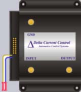
Came across something that I am considering to use for the fuel pump control on this gas turbine. It is a fuel pump controller for automotive use of which taps into the throttle position sensor and varies the pump speed based on throttle position. The throttle position sensors in most vehicles have an output voltage range from ~0.5V to 5.0V going from fully closed to fully open throttle position. The device I found is made by www.dccontrol.com and is listed in the "Other Control" menu option at the top of their main page. The device can handle up to 35A (which is likely more than any of us GT folks would ever exceed) and has adjustable base and peak POTs to allow configuration with any range of input signal (some throttle position sensors in vehicles are 0-12V).
Using one of the DAQ device's analog outputs to control this device will be very simple to do and configure. Its a bit pricey for the controller, at $145USD, but an off-the-shelf solution, with warranty, has its appeal.
I'm sitting on the fence about buying one of these after already having purchased all of the ICs necessary to construct my own controller.... The parts to build one are less than $20.....