what happened with it Larry?
it was looking good, and then no more updates!
were you able to test it?
Pablo
Maggie Muggs??
Moderator: Mike Everman
-
Psignorian
- Posts: 18
- Joined: Mon Nov 24, 2003 5:11 pm
-
larry cottrill
- Posts: 4140
- Joined: Sun Oct 05, 2003 1:17 am
- Antipspambot question: 0
- Location: Mingo, Iowa USA
- Contact:
Maggie and Me
Pablo & Psignorian -
Sorry I haven't looked in here much lately -- I just now noticed your posts. Maggie is still untested, BUT the horse barn is finished and my day job is FINALLY easing up a bit, so it looks like I should be able to start work on a decent thrust-measuring test stand for maggie.
I think I have decided to follow Ben's [and your] example and try using propane for the initial testing of Maggie, for one reason: with vapor as a fuel, I can test my ability as a jet engine designer, instead of my ability as a carburetor designer. Ha!
I have revised the Maggie Muggs site quite a bit in just the last few days. Here is a humorous gimmick to introduce your non-jet-interested friends to the site: http://bz9.com/guess [go ahead and try each of the four captions - this is supposed to be hysterically funny, naturally].
The photo I use at the top of the "new" Maggie site is posted below.
Talk to you later ...
L Cottrill
- Attachments
-
- Maggie_designer_ad2_grey_crop1.jpg
- Photo Copyright 2004 Larry Cottrill
- (286.97 KiB) Downloaded 1340 times
-
Mike Everman
- Posts: 5007
- Joined: Fri Oct 31, 2003 7:25 am
- Antipspambot question: 0
- Location: santa barbara, CA
- Contact:
-
Ray(in England)
- Posts: 72
- Joined: Thu Oct 30, 2003 1:32 pm
- Antipspambot question: 0
- Location: Nottingham
Larry
Love that photo. advert for your Maggie Mugs ramjet,Larry.
Nice to see you have returned.
Feared you'd given up on us.
Couldn't get your jet webzine to view.
Might be fault at my end,though.
Ray.
Nice to see you have returned.
Feared you'd given up on us.
Couldn't get your jet webzine to view.
Might be fault at my end,though.
Ray.
-
larry cottrill
- Posts: 4140
- Joined: Sun Oct 05, 2003 1:17 am
- Antipspambot question: 0
- Location: Mingo, Iowa USA
- Contact:
Photo and Sites
Ray -
My hosting service was battling against a DoS [Denial of Service] attack for a couple of days -- things seem to be working now.
Glad you like the photo. Some people think I should try selling it as a poster. A way to capitalize the experimental programs of Cottrill Cyclodyne Corp -- Ha! I'll bet what every girl really wants is a big picture of an old guy proclaming "because what every man really wants is A JET TO FLY."
I have bought a few parts for a propane supply with adjustable regulator. I should also be able to use that experimentally with MAPP gas. The next major item is an electric leafblower. I've decided I'll need a plenty big one -- the flow of adequate cooling air around Maggie will be just as important as the combustion air going in.
When I finally throw together my thrust measuring test stand, it will be arranged so the thrust of the blower does NOT get added in to the measured value. That way, the measured thrust will be the NET thrust after drag at a particular speed. By running the air through and around Maggie WITHOUT combustion, the true value of drag can be determined empirically. That should be a pretty accurate method of deriving what's really going on. Both total drag and net thrust will vary heavily with air speed, of course.
L Cottrill
-
Bruno Ogorelec
- Posts: 3542
- Joined: Sat Oct 04, 2003 7:31 am
- Antipspambot question: 0
- Location: Zagreb, Croatia
Re: Maggie and Me
Great photo. Good enough for a blues album cover. Welcome back, Larry!Larry Cottrill wrote:The photo I use at the top of the "new" Maggie site is posted below.
-
larry cottrill
- Posts: 4140
- Joined: Sun Oct 05, 2003 1:17 am
- Antipspambot question: 0
- Location: Mingo, Iowa USA
- Contact:
FINALLY - An Air Supply for Maggie Muggs, Crude Dry Testing
I have finally obtained what should be a suitable air supply for testing Maggie: the mighty Black & Decker Leaf Hog blower/vac. Maximum velocity is 215 MPH, which I hope will be far more than adequate. Naturally, I can't remember the CFM now, since I didn't write it down, but it seems enough for both combustion and cooling for an engine of Maggie's size. Current load is 12A at 120VAC, for a power consumption of 1440 watts. The noise is horrendous.
It is interesting to crudely evaluate this machine by blowing it across the grass, since I have a lot of experience seeing the Dynajet perform this very function. The Dynajet wins hands down, probably by a multiple of five or six! While such a judgment is highly subjective, I find it amusing that the venerable Djet, basically unchanged in design since the year I was born, moves air far better than a modern 1400 watt centrifugal fan.
Using the automotive pressure/suction gauge for preliminary testing, the maximum velocity pressure obtained at the nozzle outlet appeared to be right at 0.5 PSIG, not nearly as high as I would have thought [this was air at 70 degF, but not really 'standard air', as here in Iowa we are about 1000 ft above Mean Sea Level]. At this presumed 215 MPH velocity, it was relatively easy to push Maggie, hand-held, right up to the nozze outlet. I would estimate the maximum total drag at maybe half a pound [of course, my hand holding Maggie was part of this]. I halfway expected some kind of howl from Maggie [because of all the little holes], but all I heard was a kind of white noise roar increasing in intensity as I brought her closer in.
Now, here's the first indication of a possible design inadequacy - see what you think:
Putting the gauge on Maggie's pressure tap [the tube coming out of the bottom of the diffuser], I DO get a positive static pressure rise, but only about 0.2 to 0.25 PSIG max!!! Friends, we might as well face it -- that is not much pressure to work with. Of course, this is static pressure gain only [if you assume the design of my pressure tap is sensible] and there seems to be plenty of air getting through Maggie, so the velocity pressure component getting through the holes could be more on the order of the 0.5 PSIG measured out in front. Still, the total [static gain + velocity pressure] has to approximate the maximum gauge pressure we can maintain by combustion in the chamber. [All gauge measurements mentioned here are approximate -- it is impossible to read such small deflections on the gauge with any real precision.]
Conclusion: Sadly, it appears that the net thrust of Maggie Muggs is going to be measured in ounces, not pounds, even at a speed that is still reasonably hard to obtain. [Possibly, could THIS be the reason nobody's out there hawking low-speed ramjets?]
Now, kind reader, before you click out in total disgust, remember that Maggie's total engine weight is just 10.5 ounces. So, perhaps the problem in using Maggie as a flight engine will not be so much in net T/W ratio as in the bulk and drag of such an engine in relation to a small model that can be reasonably powered. And, of course, we might have to go to the Rocket Forum to get a launch system for our model! [Recall that what I was hoping for was an engine that could take over after a propeller-driven takeoff and acceleration to reasonable speed. A small model is not going to handle this kind of drag loading to get up to speed.]
I will know more when I get the test stand built. I'm going to make sure that I set it up to measure both total engine drag and net thrust [I can't make it do both at once, of course, but I can have it measure drag in a dry run setup for a given air setting, then fire the engine to get the net thrust]. It also looks like I'll need a force multiplier lever system to get accurate measurements, but that shouldn't be hard to rig.
Initial testing will be with propane, and I could also try MAPP gas, which is more expensive but burns hotter and faster [i.e. more rapid expansion]. Here are the beginnings of a propane fuel feed -- the regulator is adjustable over a wide range of supply pressures, and you can see where the torch head was cut off to provide a valve with the proper fitting for the small [hand torch size] propane or MAPP gas cylinders:
http://www.cottrillcyclodyne.com/2004-0 ... _small.jpg
The big cylinger stem at the left end of the regulator will come off, and the valve shown will be mounted in its place. This will provide an easily adjustable and well-regulated supply for experimentation.
L Cottrill
-
Bruno Ogorelec
- Posts: 3542
- Joined: Sat Oct 04, 2003 7:31 am
- Antipspambot question: 0
- Location: Zagreb, Croatia
Re: FINALLY - An Air Supply for Maggie Muggs, Crude Dry Test
Larry, good to see you make some progress again, even if it is not as positive as you may have hoped.Larry Cottrill wrote:I find it amusing that the venerable Djet, basically unchanged in design since the year I was born, moves air far better than a modern 1400 watt centrifugal fan.
Your quote neatly -- and powerfully -- illustrates the reason smart engineers and physicists were so excited about the pulsejet in the 1940s and 50s. Substitute a jet engine combustion chamber for Maggie and a long string of powerful axial compressors for your leaf blower and you have the engineer's dilemma.
It took a great amount of horsepower (not to mention dollars) to run those compressors, yet a puny tin tube generated the same effect for a few cents and without the complication.
Yet again I want to make this point, which so many enthusiasts miss. It all boils down to heat. A pulsejet is a much more efficient generator of heat from fuel and air than a constant-pressure jet (like a turbojet). It is more efficient because of pulsation.
The problem is, the way it produces the heat means that the hot gases that exit from the pulsejet also come in pulses, rather than in a steady stream Those pulses are very difficult to tame. All the tricks people have come up with have been inefficient.
So, pulsation first giveth and then it taketh away. Cruel.
-
Mike Everman
- Posts: 5007
- Joined: Fri Oct 31, 2003 7:25 am
- Antipspambot question: 0
- Location: santa barbara, CA
- Contact:
Larry, I see no complication with the thrust measurement setup. The reading just goes negative (or the slide or flexure or whatever will rest against hardstops) until thrust is produced. It will automatically subtract the drag of the leafblower blast, which is the number you're really after. One would hope that the thrust will exceed the drag, and the carriage will move off of the hardstops for a measureable thrust into the stream.larry wrote:I'm going to make sure that I set it up to measure both total engine drag and net thrust [I can't make it do both at once, of course, but I can have it measure drag in a dry run setup for a given air setting, then fire the engine to get the net thrust].
Certainly if you want to know the drag all by itself, and your setup is not bi-directional, then flip the motor and blower around and read it out cold, in the direction that your gage works.
I will be calibrating my leafblower on a buddy's aircraft pitot tube, so at known blast distance, I will have known airspeed simulated. Good luck!
Mike Often wrong, never unsure.
__________________________
__________________________
-
larry cottrill
- Posts: 4140
- Joined: Sun Oct 05, 2003 1:17 am
- Antipspambot question: 0
- Location: Mingo, Iowa USA
- Contact:
Mike -
Your reference to the aircraft pitot tube reminds me of how silly it was of me to expect a reasonable gauge pressure from the leaf blower airstream -- the fact is, a person blowing into an aircraft pitot tube can instantly ruin the air speed indicator [the instrument mounted in the panel], forcing it back to the shop for repair and re-certification! That should give us a clue as to the kind of pressure gain from velocity alone that we're talking about here!
For my thrust measuring setup, here's the current plan [since I need to multiply the force by a factor for accurate measurement anyway]: The pullrod hooked to the force gauge will pass THROUGH one lever to get to the other, where it will be anchored at the proper moment arm from the fulcrum point. The lever perforated by the rod will reverse the direction of pull [i.e. the fulcrum will be between the two lever ends], and a collar will be positioned on the rod so it contacts when the carriage moves rearward [the 'drag' direction]. So, when the carriage moves back, lever no. 1 pulls on the gauge thru the rod, measuring drag; when it moves forward, contact with the stop collar is lost, and lever no. 2 pulls on the gauge via the rod, measuring thrust. Seems like it ought to work.
The carriage will travel along two channels on glorified roller-skate wheels -- the emphasis will be on freedom of movement rather than precision tracking. The carriage will hold the force gauge and the diffuser pressure gauge [although now that I know better, I might replace that with a simple water manometer].
I'll try to post a picture of Maggie with the gauge attached. Not a very good shot, due to glare on the gauge face.
L Cottrill
- Attachments
-
- Maggie_with_gauge_crop1.jpg
- Photo Copyright 2004 Larry Cottrill
- (735.41 KiB) Downloaded 1234 times
-
larry cottrill
- Posts: 4140
- Joined: Sun Oct 05, 2003 1:17 am
- Antipspambot question: 0
- Location: Mingo, Iowa USA
- Contact:
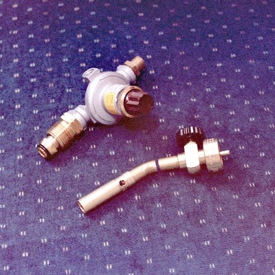
Mark, that's a Super Tigre needle valve, modified by cutting off the fancy machined stub at the 'interior' end. See the Maggie Muggs site at http://bz9.com/Maggie [the 'short link'] -- click on one of the links to Page 2 and scroll down a bit.
[Well, OK, I'll post the pics here too. Note the little cutoff section in the 'parts' photo -- it is discarded.]
L Cottrill
[Well, OK, I'll post the pics here too. Note the little cutoff section in the 'parts' photo -- it is discarded.]
L Cottrill
- Attachments
-
- Photo Copyright 2004 Larry Cottrill
- Fuel_pipe_parts_crop1.jpg (29.88 KiB) Viewed 18678 times
-
- Photo Copyright 2004 Larry Cottrill
- Fuel_pipe_finished_crop1.jpg (21.72 KiB) Viewed 18677 times
-
larry cottrill
- Posts: 4140
- Joined: Sun Oct 05, 2003 1:17 am
- Antipspambot question: 0
- Location: Mingo, Iowa USA
- Contact:
Stephen -Stephen H wrote:wow.. that is nice... u make that ?... impressive
Man, it won't go if it ain't good ;-)
Yes, I "made that", but only by buying a Super Tigre needle valve assembly for $18US and hacking the little end off with the jeweler's saw, then gluing on a couple pieces of brass model airplane tubing [with J-B Weld, naturally!] and drilling the hole through. Come to think of it, I also "ported out" the inlet and the main bore with a no. 50 drill to maximize flow. All warranties definitely voided on that one!
That $18 assembly is the single most expensive part I bought to build Maggie Muggs, and the whole engine cost only 50 bucks or so. By contrast, my new High Velocity Laboratory Air Mover [aka Black & Decker Leaf Hog] for testing it cost me $61.50 at Wal-Mart.
It's the tools that kill you.
L Cottrill
- Attachments
-
- Maggie_in_space_crop1.jpg (59.8 KiB) Viewed 18651 times