New and Improved Lady Anne
Moderator: Mike Everman
-
Irvine.J
- Posts: 1063
- Joined: Mon Jun 05, 2006 4:28 pm
- Antipspambot question: 0
- Location: Brisbane, Australia
- Contact:
re: New and Improved Lady Anne
That garage test stand is something to behold for sure. Looks great! I've had a roller system for thrust on the cards for a while now, and looking at your setup think it might be time to share it, using the water test...forgive me for using one of your drawning for this, just saved me a bit of time, this is modified to your current set up...and is probably cheaper then 2 sliding door rails or something. I think you can buy the bearings without the wheel, but I had a few lying around so i just cut one out.
- Attachments
-
- wheel.jpg
- (56.21 KiB) Downloaded 581 times
re: New and Improved Lady Anne
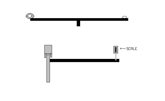
Irvine, here's an idea I've had (and will probably put to use) as the cart didn't seem to work... which was a disappointment... Here's a quick picture, shouldn't be hard to make, all it would require is a bearing, a piece of bar stock, a scale, counterbalance, and an axis. (as well as various attaching items for the PJ)
Lasers, jets, and helicopters HURAH!
-
Irvine.J
- Posts: 1063
- Joined: Mon Jun 05, 2006 4:28 pm
- Antipspambot question: 0
- Location: Brisbane, Australia
- Contact:
re: New and Improved Lady Anne
Thats a good idea mate, I would think the only think is put a bearing (or other turning thing, even if its just a loop so it can hang freely) so as the counter arm angle to the spring increases it will always be pulling at 90* to the scale, know what I mean?
Just pretend theres a bearding on the spring scale ground attachment, the scale could simply be attached with a hole and string to the swingarm if need be. It would simply mean a little more accuracy, though this looks by far the simplest method.
Knowing Larry and seeing his test rig, he'll want something really "wizzbang." His test set up is already sweet though, and almost exactly what I had in mind for applying my roller tester.
re: New and Improved Lady Anne
I dunno... (I don't get what you're saying...) I'm sure this would be accurate within the ounce.
A slight variation of this would be to just tip a push scale and put it on the opposite side of the pull scale (after removing the pull one of course). That should allow you to use a regular bathroom scale for the bigger PJ's
A slight variation of this would be to just tip a push scale and put it on the opposite side of the pull scale (after removing the pull one of course). That should allow you to use a regular bathroom scale for the bigger PJ's
Lasers, jets, and helicopters HURAH!
-
larry cottrill
- Posts: 4140
- Joined: Sun Oct 05, 2003 1:17 am
- Antipspambot question: 0
- Location: Mingo, Iowa USA
- Contact:
New and Improved Lady Anne As Built
All right, last night I got the intake shell welded on and even managed to attach the starting air pipe. All that remains now is producing a fuel tube and providing some sort of mounting lug to hold on to her.
She ended up about 6 mm longer than the plan dimension - so much for precision building! The intake flair is a hair beyond where it should be, about 2mm off the mark. I think my problem is just that marking around paper templates adds a bit to what I end up with, since I only file the cut edges back to the mark, all around. So, by the time I weld all those cones together, I guess there's that much accumulated error. This doesn't seem like much, but I want everyone to be aware of any basic differences between mine and James D's build.
So - the basic 'as built' dimensions are, approximately:
Overall length = 552 mm
Outer shell length (dome not included) = 540 mm
Dome edge to intake pipe forward edge = 43 mm
Chamber ID at dome edge = 60mm
Chamber throat ID = 29mm
Mid cone / choke cone juncture ID = 40mm
Choke cone throat ID = 32mm
Tail cone outlet ID = 62mm
Intake pipe physical length = 115 mm (rear port edge to flare rim)
Intake port (cut into chamber cone) = 36mm W x 43 mm L
Intake cross-section at rear edge of port = 36mm W x 24mm H (remember, though, the curve of the chamber wall reduces this area)
Intake cross-section at intake flare throat = semi-ellipse, 28mm W x 28mm H (again, the conical wall reduces this area)
That's about it. If James D (or anyone) is interested in a better calculation of the intake cross-section at those two points, I can probably calculate it fairly closely based on what has already been measured and the radius of the cone at those two points. I'll get a couple of photos to post later on, and I'll get some video and stills of testing (unless it's a total bust).
EDIT: Nuts - forgot to mention: Finished weight with fuel tube but without engine mount lug will be 22 ounces, almost a pound and a half (about .75 kg). A little on the heavy side for such a small motor, I think.
L Cottrill
-
larry cottrill
- Posts: 4140
- Joined: Sun Oct 05, 2003 1:17 am
- Antipspambot question: 0
- Location: Mingo, Iowa USA
- Contact:
Thrust Stand Comments
thecheat -
Your stand is a good idea. There is an excellent material for the lever arm that you can get at Lowe's or Menards or a good hardware store: Look for a steel tube about an inch square with a regular series of holes punched clear through along its length. The holes in these tubes are almost perfectly spaced, which will save some careful measuring. This is especially appealing in terms of one thing I mentioned before: levering up the force for more accurate measurement.
In other words, instead of the pivot being in the middle, imagine the engine 20 spaces out from the pivot and the scale 2 spaces out on the other side. Your scale will now measure ten times the force of the actual thrust with only about 1/10th the error in reading it! Because the holes are set up with very uniform spacing, the scaling accuracy will be high. One thing you'd need to be careful of is that your engine centerline is PRECISELY centered over a hole, i.e. your engine mount would need to be carefully built so a single bolt will center it up. Also, the pull point for the scale would need to be carefully centered on the hole used for that.
L Cottrill
Hey, thanks! :D
It's a pretty simple idea... But, I was just wondering, wouldn't it be easier if you had a one way bearing to measure thrust? I've got a couple laying around... and I'll probably use them. It'd be great to have it stay at a reading even after it's off. May make the resetting part a bit harder though...
It's a pretty simple idea... But, I was just wondering, wouldn't it be easier if you had a one way bearing to measure thrust? I've got a couple laying around... and I'll probably use them. It'd be great to have it stay at a reading even after it's off. May make the resetting part a bit harder though...
Lasers, jets, and helicopters HURAH!
New and Improved Lady Anne
Larry, I've got my fingers crossed that it works for you. However my recent testing with adjustable intake and tailpipe extension didn't yield any progress at all.
No matter what I tried I just got the same, fairly strong, resonant howling mode that would quit without forced air, and its behaviour didn't seem much different when hot, which makes me think it must be pretty far from proper running.
I think/hope your build is different enough that it might just work;)
- Attachments
-
- Heat pattern with standard (as drawn) intake length and no tailpipe extension.
- AB02_vid_still.jpg (27.09 KiB) Viewed 10362 times
New and Improved Lady Anne
This picture shows the tail pipe add on, it gives a maximum of 130mm extra length and made no noticeable difference:(
- Attachments
-
- AB02_adjustable_small.jpg (28.61 KiB) Viewed 10359 times
-
larry cottrill
- Posts: 4140
- Joined: Sun Oct 05, 2003 1:17 am
- Antipspambot question: 0
- Location: Mingo, Iowa USA
- Contact:
New and Improved Lady Anne
James -
Man ... maybe we are really just down a blind alley with this geometry. It's weird, though, that it doesn't seem to resonate at all, as Bill's design did once some adjustments were made.
One thing that occurs to me is that maybe the fuel spout location is more critical than on your original. You didn't say anything about playing with this parameter, and maybe that would be worth trying. With a straight fuel pipe like this, I had really good running on one engine with the fuel spout way in at about the 3/4 position in the intake - you might try that and some others. Even if it still won't run, you might be surprised at a difference in behaviour, sound or whatever. Just a thought.
I've got a fuel pipe ready for mine. I'll start out at that 3/4 position just mentioned. All I need yet is to weld on a solid mounting bracket to hold the engine (not that it's likely to want to go anywhere ;-).
If you get to the place where you're ready to give up on this one, try this (but there's no backing out): Test my hypothesis about the intake impedance - start pinching the intake in, little by little, just behind the flare and see if the sound or other behaviour changes. I experimented with fairly severe flattening on the intakes of my Elektra engines, and they still started and ran fine, but of course it re-proportions flows between the intake and tailpipe. If my hypothesis about low intake impedance is correct, that might be the change that will bring it in. The problem with that is, you don't seem to have sensed any evidence of resonant operation at all, which I think should be at least detectable.
L Cottrill
New and Improved Lady Anne
I'll post a video clip, It did resonate in a weak sense with forced air, just not the way it should.
Maybe the cold air coming in the intake kind of plugged it and allowed it to resonate like a closed tube? I'm not sure.
You might be right about the fuel pipe, with the first Anne Boleyn its position was quite critical, but when in the wrong place it would catch and try to resonate but then immediately die. This one doesn't seem so close although it could be a combination of small factors.
I wont be able to test it again until the new year so I'll wait until you test yours before I pinch the intake.
This video clip is fairly typical of what I got, regardless of intake length, etc.
- Attachments
-
- AB02_156mm_intakeLength.wmv
- (1.03 MiB) Downloaded 3322 times
-
larry cottrill
- Posts: 4140
- Joined: Sun Oct 05, 2003 1:17 am
- Antipspambot question: 0
- Location: Mingo, Iowa USA
- Contact:
New and Improved Lady Anne
James -
Yes, the video makes it seem like it's just "on the edge" where it could tip over and go. This is really a strange one.
Oddly enough, though our intakes should be acoustically close to identical, there are some differences that might make my design "better" in this case. As you mentioned earlier, it is slightly "tapered", meaning that the passage area decreases as you go from the chamber port to the throat behind the flare. And, of course, the passage at the flare is smaller than the area of your straight tube intake ID. So, overall, my intake should have a higher impedance for the air going out, with a little "back pressure" because of the nozzle action of the tapered design. Doesn't seem like much of a difference, but this might be just the kind of situation where "little things mean a lot". We'll see.
Unfortunately, we are now in the grip of generally lousy weather - not really cold yet, but damp, foggy, rainy and all that. Snow in a few days, maybe, but at least after that the relative humidity might be down. As long as I can work in the garage for short sessions without my hands freezing up, I can still get a little bit accomplished in winter.
L Cottrill
You might find it interesting that a likely OCF has been moved from the former 324 Hz to 381 Hz (2 samples; 3rd is present, but vanishes in noise).
The above beeing valid, of course, when comparing the latest record of "James D" to records in the first "Anne Booleyn" thread, which depict the engine with inlet further downstream.
Furthermore, there were further peaks found in the spektrum than they were observed in other videos referred to above. But this might just be kind of a coincidence due to the lower peak amplitudes. Which is quite equal to the expression that "pressure history" is not supported properly, i.e. segment locations and/or dimension are in part unsuitable.
mk
-
Eric
- Posts: 1859
- Joined: Sat Oct 04, 2003 1:17 am
- Antipspambot question: 0
- Location: United States
- Contact:
I had a chinese engine that would run like that with the nice vortex at the tail end, but it was only doing it with a certian injector and injector depth range.
Did you try pulsing the flow by hand, if you have a squeeze valve and could get it 6 or 8 pulses a second that would probably help a lot.
The heat patterns really do a good job of showing the splash zone for the intake air.
Eric
Did you try pulsing the flow by hand, if you have a squeeze valve and could get it 6 or 8 pulses a second that would probably help a lot.
The heat patterns really do a good job of showing the splash zone for the intake air.
Eric

Talking like a pirate does not qualify as experience, this should be common sense, as pirates have little real life experience in anything other than smelling bad, and contracting venereal diseases
-
larry cottrill
- Posts: 4140
- Joined: Sun Oct 05, 2003 1:17 am
- Antipspambot question: 0
- Location: Mingo, Iowa USA
- Contact:
First Test of Rev 03
Well, I had about an hour and a half free this afternoon, and it was about 40 degF outside, so I welded on the engine mount and tried it. Basically:
- It would not sustain
- BUT, it DID roar a lot (actually, scream is more like it - I just can't get over the high frequency operation of this tube design!)
The engine would scream over a wide range of fuel and air pressures (i.e. regulator settings), BUT the throttleable range was extremely small - very little valve movement between not firing, roaring and finally, rich extinction. You had to have a pretty fine touch on the valve to find just the right spot. No matter what I did with the pressures, it would die instantly once I let up on the air. I also got several good bangs while feeling around for the perfect setting - actually rocked the engine on the mounting a little. Heating of the chamber during roaring mode appeared to be the beginnings of the typical FWE pattern.
One thing that was quite fascinating was that the engine would roar in two distinct frequencies, about a half-step apart on the piano keyboard! The tiniest variation in fuel valve setting would switch it between these, with the lower fuel flow giving the lower frequency. Pretty strange - I probably would have learned more if I had gone back to my needle valve, but I was still using the ball valve I had installed for Guinevere. The odd form of the starting air tube puts my hand right next to the engine body. Not only did this give a gradually intensifying "roasting" perception, but I could feel some pretty good knocks into the back of my hand on every one of the bangs produced!
James D - I'm convinced that the only really important difference between your tests and mine is the fuel spout location. Please try it again with the fuel spout way in, at about the 3/4 point, then let us know if you get something like what I saw today. James, from what I saw today, she was THAT CLOSE to taking off and going - I'm almost sure that an inch of length, maybe less, would have made the difference! The small throttle range is discouraging, however.
I shot video of the whole thing, but it will take days to get this in the form of files that can be uploaded, since it has to be done by a friend at work. What I CAN do on my own, right here at home, is make an audio file - all I need to do is get the proper cable to link the camcorder to the sound card on this computer. So, I'll try to come up with a cable and provide a short sound file, sometime in the next day or two.
MERRY CHRISTMAS TO ALL !!!
L Cottrill