relevant wd's
Moderator: Mike Everman
-
WebPilot
- Posts: 3716
- Joined: Tue Dec 07, 2004 6:51 pm
- Antipspambot question: 0
- Location: 41d 1' N 80d 22' W
relevant wd's
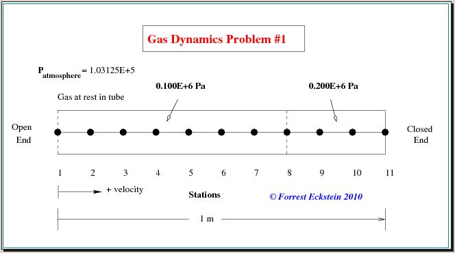
I've decided to first draw up a diagram for the code analysis I did in nonsteady-flow. I can use this to help me locate a "bug" I think exists in the program.

-
WebPilot
- Posts: 3716
- Joined: Tue Dec 07, 2004 6:51 pm
- Antipspambot question: 0
- Location: 41d 1' N 80d 22' W
Re: relevant wd's
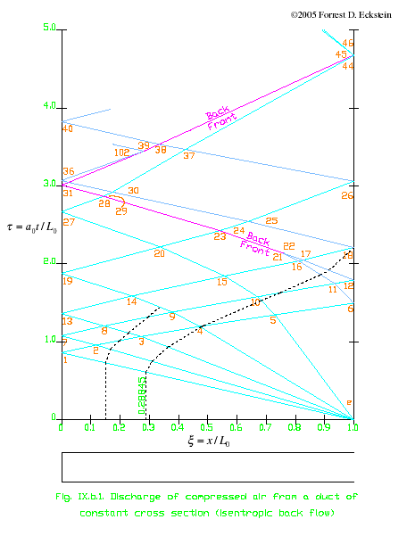
This is my previous diagram for a tube with a frangible diaphragm at the very end of a constant area tube. Read my thread entitled, Dimensionless Space and Time, for its development.


-
WebPilot
- Posts: 3716
- Joined: Tue Dec 07, 2004 6:51 pm
- Antipspambot question: 0
- Location: 41d 1' N 80d 22' W
Re: relevant wd's
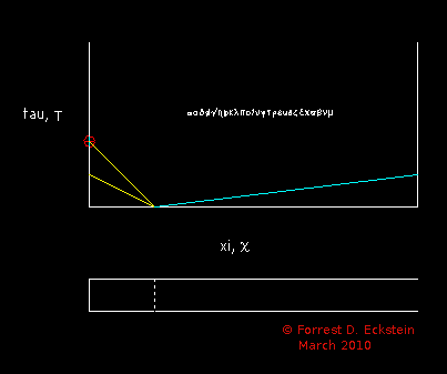
Note, the difference between the two is that the axial length of the region of higher pressure area is shorter in the tube now under consideration.

-
WebPilot
- Posts: 3716
- Joined: Tue Dec 07, 2004 6:51 pm
- Antipspambot question: 0
- Location: 41d 1' N 80d 22' W
Re: relevant wd's
My prior one and the ones to follow are much more in depth than the simple one Franco Marcenaro did.

-
WebPilot
- Posts: 3716
- Joined: Tue Dec 07, 2004 6:51 pm
- Antipspambot question: 0
- Location: 41d 1' N 80d 22' W
Re: relevant wd's
The previous pic is just a sketch showing the short in length high pressure area and the waves that are produced when the frangible diaphragm is broken. It creates a left traveling expansion fan (yellow) and a right traveling compression wave (blue).
I'll generate the numbers to support the drawing unlike that found in FM's work.
I'll generate the numbers to support the drawing unlike that found in FM's work.

-
WebPilot
- Posts: 3716
- Joined: Tue Dec 07, 2004 6:51 pm
- Antipspambot question: 0
- Location: 41d 1' N 80d 22' W
Re: relevant wd's
To do the numbers by hand, I've changed the problem slightly again.
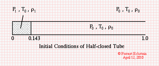
Figure 1: Initially.
- I've assumed:
- constant area tube, closed at left end and open at right
- tube is filled with air, γ is 1.4
- a pressure 2 times atmospheric is contained at the left end by a frangible diaphragm
- length of this area is only 14.3% of the total length of tube.
- air in rest of tube is at atmospheric pressure

Figure 1: Initially.

-
WebPilot
- Posts: 3716
- Joined: Tue Dec 07, 2004 6:51 pm
- Antipspambot question: 0
- Location: 41d 1' N 80d 22' W
Re: relevant wd's
At some time, the frangible diaphragm is burst ... creating a centered expansion wave fan
moving to the left and a compression wave moving to the right. Only the "head" of the centered
expansion wave is shown presently.
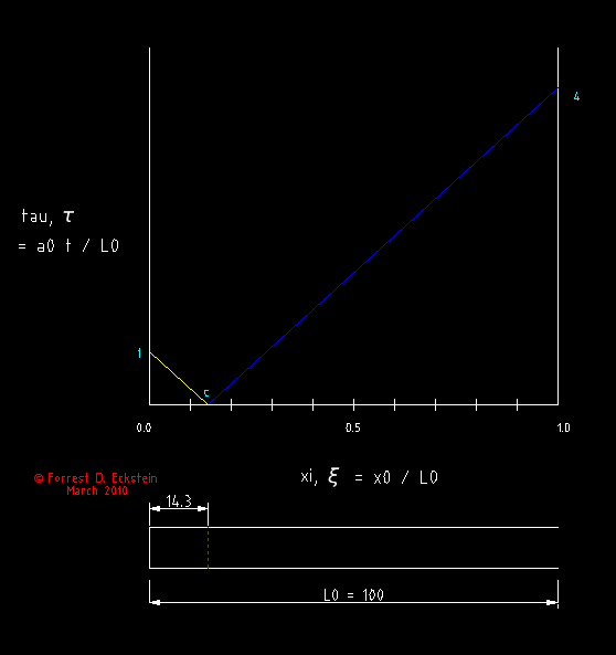
Figure 2: Frangible Diaphragm Bursts.
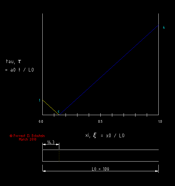

moving to the left and a compression wave moving to the right. Only the "head" of the centered
expansion wave is shown presently.

Figure 2: Frangible Diaphragm Bursts.


-
WebPilot
- Posts: 3716
- Joined: Tue Dec 07, 2004 6:51 pm
- Antipspambot question: 0
- Location: 41d 1' N 80d 22' W
Re: relevant wd's
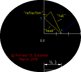
The "head" of the centered expansion wave is reflected at the inner wall. The velocity of the flow here is zero. I shall then be able to draw the "tail", but these two waves will interfere with each other before the "tail" reaches the inner wall.


-
WebPilot
- Posts: 3716
- Joined: Tue Dec 07, 2004 6:51 pm
- Antipspambot question: 0
- Location: 41d 1' N 80d 22' W
Re: relevant wd's
The previous was exaggerated to make a point.
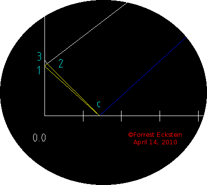
Here the "tail" of the centered expansion wave, c2, is drawn in accurately and so is part of the reflected wave, 12. These two waves interact with each other somewhat. This is shown by a difference in slope after passing through pt. 2.
NOTE on NOTATION:
Here the "tail" of the centered expansion wave, c2, is drawn in accurately and so is part of the reflected wave, 12. These two waves interact with each other somewhat. This is shown by a difference in slope after passing through pt. 2.

NOTE on NOTATION:
- When I type an ordered pair in bold, e.g. 12, it means the directed line segment from pt. 1 to pt. 2. Naturally, the pair, 21, signifies segment in the opposite direction.
These are also known as vectors.

-
WebPilot
- Posts: 3716
- Joined: Tue Dec 07, 2004 6:51 pm
- Antipspambot question: 0
- Location: 41d 1' N 80d 22' W
Re: relevant wd's
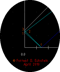
This shows the reflection of expansion wave, 23, by left wall.
Naturally, it is reflected as an expansion wave.
Naturally, it is reflected as an expansion wave.


-
WebPilot
- Posts: 3716
- Joined: Tue Dec 07, 2004 6:51 pm
- Antipspambot question: 0
- Location: 41d 1' N 80d 22' W
Re: relevant wd's
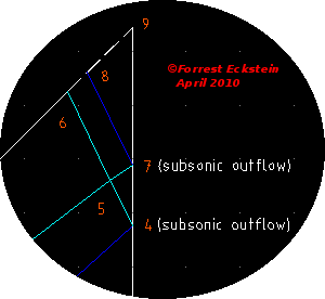
These three waves are reflected at the right boundary and interfere
with each other. The following shows work I've accomplished, so far.
with each other. The following shows work I've accomplished, so far.


