relevant wd's

Moderator: Mike Everman

WebPilot
Posts: 3716
Joined: Tue Dec 07, 2004 6:51 pm
Antipspambot question: 0
Location: 41d 1' N 80d 22' W

Re: relevant wd's

Post by WebPilot » Fri May 07, 2010 6:27 am

Image

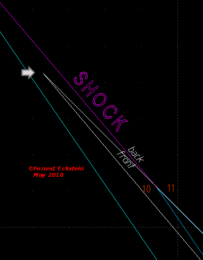
 Here the arrow points to the revised location (from Revision A) of points 10 and 11, where the compression waves from the right end, depicted in white (), converge to form a Q Shock wave.
Image

WebPilot
Posts: 3716
Joined: Tue Dec 07, 2004 6:51 pm
Antipspambot question: 0
Location: 41d 1' N 80d 22' W

Re: relevant wd's

Post by WebPilot » Mon May 10, 2010 5:03 pm

Image

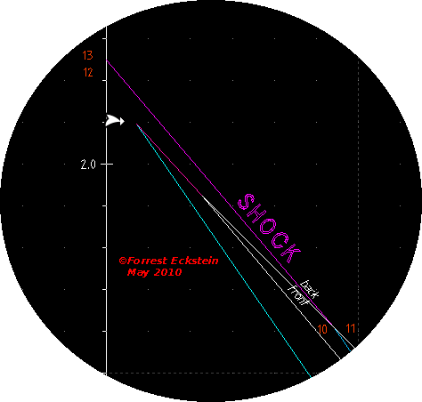
 Unfortunately, the revised SHOCK wave overtakes the expansion wave. The latter is absorbed by the former.

 The old is retained for comparison purposes.
Image

WebPilot
Posts: 3716
Joined: Tue Dec 07, 2004 6:51 pm
Antipspambot question: 0
Location: 41d 1' N 80d 22' W

Re: relevant wd's

Post by WebPilot » Tue May 11, 2010 2:44 am


 So, the present analysis fails to predict the continuation of a cycle:

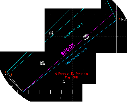
 I tried to simplify the calculation by not modeling the right propagating wave at the pressure discontinuity as a shock and a contact discontinuity as it should be. I did model it as a simple compression wave. This now seems too simplistic.
Image

WebPilot
Posts: 3716
Joined: Tue Dec 07, 2004 6:51 pm
Antipspambot question: 0
Location: 41d 1' N 80d 22' W

Re: relevant wd's

Post by WebPilot » Wed May 12, 2010 4:45 pm

 Revision C ...
Image

paul fellows
Posts: 99
Joined: Sat Mar 13, 2010 4:15 pm
Antipspambot question: 125
Location: middlesbrough

Re: relevant wd's

Post by paul fellows » Thu May 13, 2010 8:45 pm

You seem to have assumed that the second wave, the one that reflected of the end wall / valve plate, will continue to catch up with the first wave after they are reflected from the open end of the tail pipe. :?
I suspect that it will in fact start to fall behind. :)
Whilst they are travelling towards the open end both gasses are travelling 'with the wind', with the mass flow of gas. After the turnaround they will be travelling into the wind, but the second wave will be travelling into a slightly faster wind. The first wave speeds up the out flow of gas as it starts its first inward journey. :)
This difference in speed of the two waves will be further increased at the valve end because the second wave will have more cold air to pass through. :D
So to get resonance you will need for both waves to arrive back at the point that they started at having travelled exactly twice the length of the tube.

i could be be compleatly wrong :(
i often am :lol:
two test tickles

WebPilot
Posts: 3716
Joined: Tue Dec 07, 2004 6:51 pm
Antipspambot question: 0
Location: 41d 1' N 80d 22' W

Re: relevant wd's

Post by WebPilot » Fri May 14, 2010 2:27 am

I have made very few assumptions here; air at STP, a relative length for the high pressure region, and a pressure ratio for that region.

I just let the mathematics work out its solution. IOW, I an using the MOC solution to the Euler 1D compressible flow equation (hyperbolic non-linear partial differential equation)

My only concern is that a rarefaction wave has to strike the valve end first before a compressive shock strikes at a later time to stop the inflow.

I am hoping my Revision C gives me just that.

PS Wave speeds in the diagram are inversely proportional to slopes, i.e., a faster wave speed results in a shallower slope; a slower speed, a steeper slope.
Image

WebPilot
Posts: 3716
Joined: Tue Dec 07, 2004 6:51 pm
Antipspambot question: 0
Location: 41d 1' N 80d 22' W

Re: relevant wd's

Post by WebPilot » Wed May 19, 2010 1:05 am

Image

 Here, for revision "C", I have only drawn the initial, right moving, right facing, P-shock as it travels to the right end from the ruptured diaphragm. For comparison purposes, I've not erased the previous compression wave model.
Image

WebPilot
Posts: 3716
Joined: Tue Dec 07, 2004 6:51 pm
Antipspambot question: 0
Location: 41d 1' N 80d 22' W

Re: relevant wd's

Post by WebPilot » Thu May 20, 2010 1:10 am

 Notice, the shock travels somewhat slower than the previously modeled compression wave, and its slope is thus "steeper".
Image

WebPilot
Posts: 3716
Joined: Tue Dec 07, 2004 6:51 pm
Antipspambot question: 0
Location: 41d 1' N 80d 22' W

Re: relevant wd's

Post by WebPilot » Thu May 20, 2010 4:28 pm

Image
Image

WebPilot
Posts: 3716
Joined: Tue Dec 07, 2004 6:51 pm
Antipspambot question: 0
Location: 41d 1' N 80d 22' W

Re: relevant wd's

Post by WebPilot » Fri May 21, 2010 1:14 am

 Differences in modeling.
  • a compression wave () is reflected at an open boundary as an expansion wave, but
  • the shock () is reflected as an expansion wave fan.
Image

WebPilot
Posts: 3716
Joined: Tue Dec 07, 2004 6:51 pm
Antipspambot question: 0
Location: 41d 1' N 80d 22' W

Re: relevant wd's

Post by WebPilot » Sun May 23, 2010 12:35 am

 In revision C, I am modeling a right moving, mild shock wave and taking advantage of its being reflected at the open end as an expansion wave fan.
Image

WebPilot
Posts: 3716
Joined: Tue Dec 07, 2004 6:51 pm
Antipspambot question: 0
Location: 41d 1' N 80d 22' W

Re: relevant wd's

Post by WebPilot » Sun May 23, 2010 7:42 am

Image
Image

WebPilot
Posts: 3716
Joined: Tue Dec 07, 2004 6:51 pm
Antipspambot question: 0
Location: 41d 1' N 80d 22' W

Re: relevant wd's

Post by WebPilot » Sun May 23, 2010 5:08 pm

 Above shows the head and tail of the expansion wave fan created by the weak shock being reflected at the open end of the tube.
Image

WebPilot
Posts: 3716
Joined: Tue Dec 07, 2004 6:51 pm
Antipspambot question: 0
Location: 41d 1' N 80d 22' W

Re: relevant wd's

Post by WebPilot » Mon May 24, 2010 4:18 pm

 I've advanced the drawing last night.
Image

WebPilot
Posts: 3716
Joined: Tue Dec 07, 2004 6:51 pm
Antipspambot question: 0
Location: 41d 1' N 80d 22' W

Re: relevant wd's

Post by WebPilot » Tue May 25, 2010 3:36 am

Image
Image

Post Reply